Discover a bedroom designed to perfection by Aartigallery

Bedroom Interior Design

Washroom design

Prime Videos
Latest Uploads


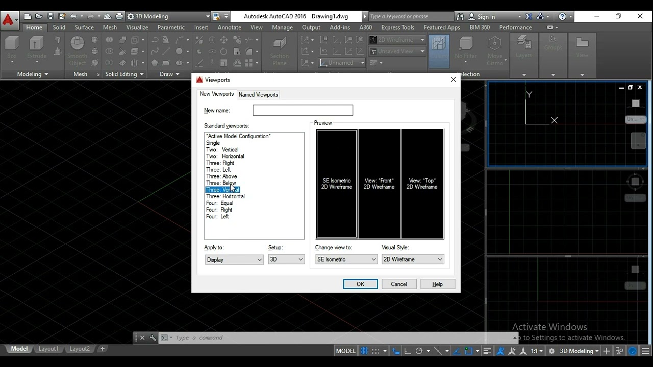
Find out more about AutoCAD for interior design and how you can improve your design skills with us.
Interior design is big business, and when you’re working with clients, they expect the best. That’s why mastering digital tools and software like AutoCAD for interior designers is essential if you want to make a name for yourself in this industry.
In this training, we’ll show you how computer aided design (CAD) drawing solutions AutoCAD and others can transform your designs. We’ll also cover why you should consider taking AutoCAD classes for interior designers before you even accept your first job in the field and how you can get started straight away on your own projects by learning some basic AutoCAD steps.

Discover a bedroom designed to perfection by Aartigallery

Washroom design

Pooja Room Interior

Bedroom Interior Design

Discover a bedroom designed to perfection by Aartigallery

Washroom design
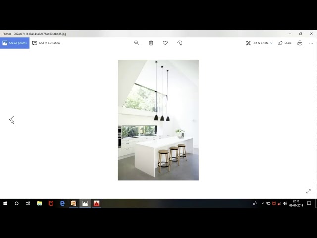
Modular Kitchen Designing
A modular kitchen is simply a modern and flexible way to design your kitchen, giving you a opportunity to learn modular kitchen designing with us and explore your visualization and designing skills ...
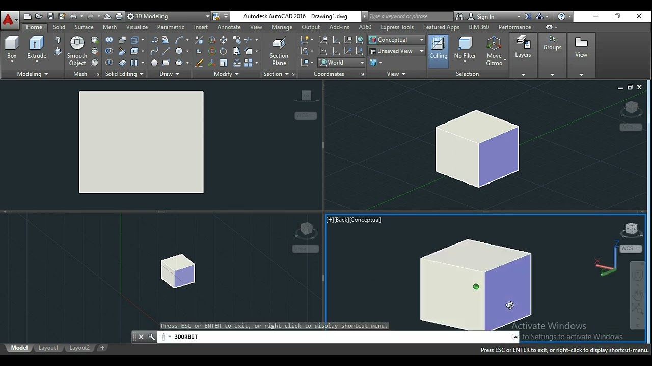
Modular Kitchen Design with AutoCAD
Modular Kitchen Design with AutoCAD


#Modular Kitchen Interior 3D with Auto CAD video Tutorial by aartigallery

Modular Kitchen Interior 3D space planning video tutorial by aartigallery
Modular Kitchen Interior with AutoCAD 3D episode 4 - 2D to 3D Modelling by aartigallery